Line coding
With line coding, it is possible to represent sequences of bits using digital signals. Among the line codings we have: unipolar, polar, bipolar, multilevel, and multiline.
Nyquist theorem
In a channel without noise, this theorem gives us the maximum velocity at which we can send bits: Nmax = 2 × B × log2 L
where B is the bandwidth and L is the number of signal levels used to represent the data.
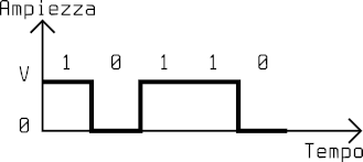
Unipolar code NRZ
The NRZ (Non-Return-to-Zero) code represents 1 as a positive voltage and 0 as a null voltage. It is called NRZ because the signal does not return to zero while coding each bit.
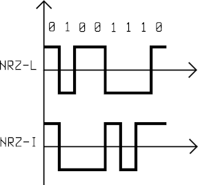
Polar code NRZ
In a polar code, two levels of voltage are used: positive and negative. In NRZ-L (Level) a positive voltage represents 0 and a negative voltage represents 1. In NRZ-I (Invert) the bit is determined by a change in the voltage level: absence of change means 0, change means 1.
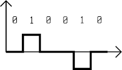
Bipolar code AMI
The AMI (Alternate Mark Inversion) code represents 0 as a null voltage and 1 as switches between positive and negative voltages.
Switching
Switching is a convenient method to connect nodes in a very large network where special nodes, called switches, are connected together and can create connections between two or more stations connected to the switches. There are three categories of switching networks: circuit switching, packet switching, and message switching.
Circuit switching networks
A circuit switching network has a collection of switches connected together with links divided into multiple channels thanks to multiplexing. The communication between two stations requires three steps:
- Connection setup, where a path is found on the links between the switches and a channel is reserved for each link.
- Data transfer, where all the channels dedicated to the connection remain unavailable to other connections.
- Connection teardown, where a station sends a signal to every switch to free their resources.
Using a circuit switching network is not the best for efficiency: we could have long periods of inactivity with no data transfers, which means wasting those resources dedicated to the connection. On the other hand, the delay is minimal: since a path is dedicated when establishing a connection, data flow without stopping at each switch.
Packet switching networks
In this network, data need to be split into packets independent from each other, namely datagrams, with variable or fixed length depending on the protocol. Switches here are also called routers. A message can be subdivided into more datagrams which can travel on different paths and reach their destination in a different order, or they can get lost, or get eliminated due to a shortage of resources on the network.
Datagram networks have no connection, meaning that switches do not keep track of connection states. There is no connection setup nor teardown. In order to know how to send a datagram, switches maintain dynamic routing tables periodically updated. From an efficiency perspective, packet switching networks are better than circuit switching networks: resources are allocated only when there are packets to transfer. The delay however can be higher: each packet could follow longer paths or need to wait in switches before being forwarded.
Multiple access protocols
With random access protocols, stations do not have control over the medium and its usage is competed for. Stations can check the state of the medium at any time and there is no access order. There could be cases where two or more stations try sending simultaneously, causing a collision which destroys or modifies the frames. Among random access protocols we have: ALOHA; CSMA; CSMA/CA; CSMA/CD.
Aloha
In the original ALOHA protocol, each station sends a frame whenever it wants, therefore there are chances of collisions. We rely on feedback from the recipient and, if it does not come, the recipient will send the frame again. Before resending a frame destroyed by a collision, stations need to wait a random amount of time, namely backoff time or Tb. After a maximum number of transmission attempts, Kmax, stations must desist and retry later.
CSMA
The Carrier Sense Multiple Access method tries to improve network performance by minimizing collision probabilities by making stations check the state of the medium before sending data. If two stations check the medium and find it free at the same time, a collision can still happen if both stations choose to transmit. There are three methods which can determine the behavior of the stations:
- 1-persistent: if the medium is busy, the station continues to check the state until it becomes free to send data.
- non-persistent: if the medium is free, the station sends data, otherwise it waits a random time before repeating the same operation.
- p-persistent: if the medium is busy, the station continuously checks the state until it becomes free, then:
- it sends the frame with probability
p. - it waits, with probability
1-p, for at least the maximum propagation time before checking the medium again. At this point, if the medium is free it restarts from 1, otherwise it performs a backoff operation.
- it sends the frame with probability
CSMA/CD
The CSMA/CD (collision detection) method adds an algorithm to detect and handle collisions. A station, while sending a frame, continuously checks the medium and if it detects a collision, stops transmitting immediately. In order to be effective, it is important that the minimum transmission time of any frame is at least twice the maximum propagation time. Otherwise, stations could not detect all collisions.
Tfr ≥ 2·Tp
CSMA/CA
The CSMA/CD method is not effective in a wireless network, where signal energy loss during transmission could negatively affect collision detection. The CSMA/CA (collision avoidance) protocol avoids collisions with three strategies:
- spacing between frames: when a station finds the medium available, before transmitting, it waits for a period of time, namely interframe spacing (IFS).
- collision window: a station that has just finished waiting for IFS waits again for a random number of intervals. After each interval, it checks the state of the medium and if it is busy, pauses this process and restarts it later when the medium is free again.
- controls: guarantee that the receiver has received the frame and no collisions have happened.
Controlled access
With controlled access protocols, stations agree on the usage of the medium. There are three methods:
- Reservation: stations need to reserve a time interval during which they can transmit.
- Polling: one of the stations controls the medium and the other stations follow its instructions.
- Token passing: stations are organized as a logic ring and access to the medium is allowed only when a station has the token, a special frame, which circulates among the stations.
Channelization
In channelization the bandwidth is shared between the stations. Among channelization protocols we have:
- FDMA, where the bandwidth is subdivided into non-contiguous sections assigned to the stations.
- TDMA, where the channel is used by one station at a time.
- CDMA, where the medium carries all transmissions simultaneously, isolated thanks to an encoding system.
Spread Spectrum
In Spread Spectrum techniques, signals of various sources are combined to prevent detection and interference. Those techniques are based on redundancy, increasing the width of the original bandwidth.
Frequency Hopping Spread Spectrum
Frequency Hopping Spread Spectrum (FHSS) selects carrier frequencies pseudo-randomly, modulated by the original signal. A third-party does not know on which frequencies data are transmitted and impeding the transmission is difficult since it would require generating interference on multiple frequencies.
Direct Sequence Spread Spectrum
Direct Sequence Spread Spectrum (DSSS) maps every bit of the original signal to a wordcode of n bits through a hopping code. Wireless LANs use Barker code, where n is 11, which means that the required bandwidth is 11 times larger.
Error Control in Data Link Layer
Stop-and-wait ARQ
The Stop-and-wait ARQ protocol is an improvement to the stop-and-wait. After transmitting a frame, the sender waits for an acknowledgement (ACK) from the recipient. At this point, the Automatic Repeat reQuest (ARQ) mechanism checks for errors. The data frame and ACK frame have a 1-bit field for a sequence number, so it can be either 0 or 1. The recipient does not send any feedback for damaged or out-of-order frames. After waiting for the ACK for a certain amount of time, the sender re-transmits the frame. This protocol is quite inefficient as the communication channel will handle at any time at most one frame, therefore we would not use its full transmissive capacity.
Go-back-N ARQ
The Go-back-N ARQ protocol manages to send more than one frame, keeping a copy for each one if re-transmission is needed, discarding them when their relative ACK frame is received. It uses m bits for the sequence number field, so its values are within [0, 2ᵐ - 1]. The sender maintains a sliding window for these values, with size Sₗₑₙ = 2ᵐ - 1, and two indices: Sₚ pointing to the first frame still waiting for the ACK and Sₙ pointing to the next frame to send. The recipient, on the other hand, has a window of size 1 as it is only interested in one ordered frame, while discarding any other.

Go-back-N ARQ sender sliding-window with m = 3
When the time for the ACK of a frame is over, the Sₙ index goes back (go-back) to the first frame without an ACK. In a channel with a high frequency of errors, this protocol would be inefficient: a damaged frame could mean re-sending many frames, resulting in a slowdown of the transmission.
Selective Repeat ARQ
The Selective Repeat ARQ protocol solves the Go-back-N ARQ problems by avoiding re-sending the frames which arrive out of order, focusing only on the damaged ones. Both sender window and recipient window have size 2ᵐ⁻¹. This means that frames can arrive out of order without being discarded by the recipient.
Network switches
Network switches are used to connect together multiple networks. They can operate at various layers of Internet:
- below the physics layer: passive hubs;
- at the physics layer: repeaters and active hubs;
- at the physics and link layer: bridges;
- at the physics, link and network layer: router;
- at all layers: gateway.
Passice Hubs
Passive hubs are simple connectors between wires. They do not amplify the signal and do not need power supply.
Repeaters and Active Hubs
A signal traveling within a wire is subject to attenuation which can affect the integrity of data. Repeaters receive a signal before it degrades, they regenerate and forward it again. Active hubs are simply repeaters with multiple ports and are useful for star networks.
Bridge
A bridge, as well as having the same capabilities as a repeater, can check source and destination addresses in a frame and figure out which port to forward it to, through a forwarding table. In a transparent bridge, the forwarding table is built automatically based on the traffic on the network.
Router
A router operates on the network layer sending packets based on logic addresses. They are commonly used to connect LANs or WANs to the Internet.
Gateway
A gateway is able to read and interpret messages from applications, therefore it could be used to connect two networks based on different models.
Address resolution
With address resolution protocols it is possible to obtain the logical address corresponding to a physical address and vice versa.
Address Resolution Protocol
Address Resolution Protocol (ARP) allows a node to discover the physical address associated with a particular logical address. Those requests are sent in broadcast while the response is sent in unicast from the unique node which corresponds to that logical address.
Reverse Address Resolution Protocol
Reverse Address Resolution Protocol (RARP) enables a node to find its logical address from its own physical address. This protocol is obsolete and it has been replaced by BOOTP and DHCP.
Bootstrap Protocol
Bootstrap Protocol (BOOTP) works in the application layer and is based on a node of the network called a relay agent which knows the IP address of the BOOTP server. It is not dynamic because the associations between addresses are based on static tables manually managed by the administrator.
Dynamic Host Configuration Protocol
Dynamic Host Configuration Protocol (DHCP) allows both static and dynamic allocation of IP addresses and it is compatible with BOOTP. A server using this protocol has a database to store static addresses and a database to store dynamic addresses.
Routing protocols
Routing protocols allow routers to communicate between each other for updating routing tables. There are protocols for intra-domain (Routing Information Protocol, Open Shortest Path First) and inter-domain (Border Gateway Protocol) routing.
Distance-vector routing protocol
In the Distance-vector routing protocol every node maintains a vector with the minimum distance between other nodes. At the beginning, nodes know only the distance from the nodes they are directly connected to, but by sharing their routing tables with nearby nodes they can discover the topology of the entire network. Routing Information Protocol (RIP) is based on a distance-vector and it is trivial as it assumes that the cost of hopping from one node to another would always be one.
Link-state routing protocol
In the Link-state routing protocol every node builds its own routing table interpreting the entire network as a graph with Dijkstra's algorithm. At the beginning, every node has a partial knowledge of the network, with nearby nodes, and shares that information with other nodes by sending packets called Link State Packets (LSP). The Open Shortest Path First protocol is based on the link layer.
Path-vector routing protocol
Inter-domain routing is based on the Path-vector protocol, where the various autonomous systems have a special node which shares its own routing table with nearby autonomous systems. The routing table will contain all possible destinations and the paths to reach them. The Border Gateway Protocol is based on a path-vector.